V-USB MIDI expression pedal with capacitance sensor
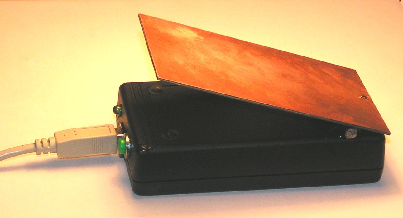
First version of the pedal
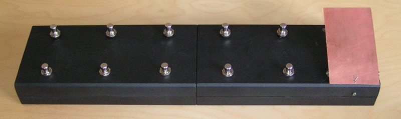
Third version of the pedal - with 10 programmable footswitches
polska wersja tego dokumentu
I wanted to built cheap, almost indestructible and smoothly working pedal manipulator which
could be used as an MIDI expression pedal for guitar effects (e.g. in
jack-rack,
guitarix
or rakarrack)
or for synthesizer
(e.g. in ZynAddSubFx or in
LMMS).
The standard ones, which use potentiometers to sense
the position of the pedal are usually neither silent nor durable.
Therefore I have decided to try another approach - the capacitance sensor.
It appears, that current microprocessors allow to easily build simple
capacitance sensors with sufficient resolution and accuracy.
My variable capacitor consists of two copper plates (eg. non-etched PCB) with dimensions
60mmx90mm. They are connected with the hinge, so the mean distance between them may be changed
(see the figure below). In fact the first plate is mounted inside of the plastic case, and the
second one outside of the case, to prevent shorting.
I was not able to find smothly moving hinge, so I've built one myself, using the brass pipes -
one with external diameter of 5mm, and the second one with internal diameter of 5mm.
The capacitance is measured in a very simple way. The PWM in the microcontroller generates
the square wave. The variable capacitance of my sensor creates the low-pass RC circuit with
the external 1.5MΩ resistor. The integrated (and therefore delayed) signal is connected
to the input capture system of the
microcontroller, and the delay of between the slopes of the PWM signal and the ICP1 signal is measured
(see the circuit diagram,
or download the schematic sources
in the KiCad format).
It appeared, that this approach provided reasonable resolution and accuracy for MIDI expression pedal,
however it is necessary to calibrate the pedal before use. To perform calibration, a simple user
interface, consisting of single push button and single LED was added to the system.
The calibration procedure is embedded in the firmware:
After the pedal is connected to the USB interface, the LED flashes quickly.
You should press the pedal fully and press the calibration button
(still holding pedal down)
when the LED starts to light continuously, release the button, still holding
the pedal down. The LED will switch off. After the first stage of calibration
is completed, LED will start to flash slowly. Then you should release the pedal
After a few seconds press the button again (with released pedal), starting the second stage of calibration.
When the LED starts to light continuously, release button (pedal should be released all
the time).
The LED will switch off during the second stage of calibration. After the second stage
of calibration is completed, LED will
start to flash shortly every ca. 2 seconds - the pedal will be ready.
The calibration procedure may be repeated - just press the pedal, press the button again
and repeat procedure from step 2.
Currently pedal operates quite reliably, however its characteristics is nonlinear (as C is inversely proportional
to the distance between the plates). To improve linearity, you can either keep the ratio between the
maximal and minimal distances small (by mechanical design), or you can add the linearization procedure into
the firmware.
You can download full firmware sources of my design, available
under the GPL license.
Please note, that my firmware is heavily based on the GPL'ed
V-USB-MIDI
project, which in turn is based on the
V-USB project.
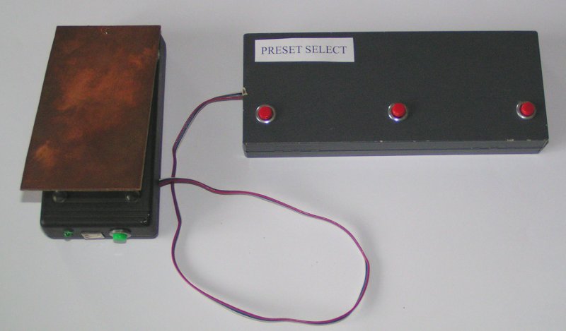
Version 2 - with footswitches support
I have also prepared the new, upgraded version which allows to use footswitches to select
presets in rakarrack or guitarix (or in ZynAddSubFx).
Three foot switches are connected to the connector P2
(see schematic diagram or
sources of schematic diagram in KiCad format).
When one pin (1, 2 or 3) is shorted to the ground (pin 4), the pedal sends
the "program change" MIDI message with program number 0, 1 or 2.
The sources of firmware version 2, with footswitches support are available
here.
Version 3 - with programmable support for up to 10 footswitches
To fully utilize the microcontroller used in the pedal, I have developed
the 3rd version, which supports up to 10 footswitches (the schematic diagram
is available
as a PDF file
and
as sources in KiCad format.
Please note, that in the new version of KiCad atmel.lib library the symbol ATMEL8-P is changed.
Therefore to avoid corruption of the schematic diagram, please download the
old version
of this library to the same directory, in which you put the schematic file.
).
Certainly you need to put the device in a bigger enclosure to mount 10 footswitches
in a convenient way.
To make my pedal more versatile, I have added reprogrammability of the pedal controller
and of all switches.
After the pedal is connected to the USB host, the pedal controller sends "control change"
messages with control number set to 0x70, and pressing of each footswitch
sends the "program change"
message with program number corresponding to the number of the switch. The release
of any switch does not generate any MIDI message.
You can easily modify MIDI messages sent at the change of position of the pedal controller,
and at pressing
and releasing of any footswitch. It allows you to use pedal to control different
functions of the software (e.g. the "modulation controller"), and to use footswitches
e.g. to control "looper" in guitarix and rakarrack or to switch on and off different effects.
Programming is performed by sending special USB packets to the endpoint 0 of the device.
If you want, you can modify the software to use MIDI System Exclusive messages for that purpose,
but I've decided to use simpler approach based on control transfers, as it allows mi to
reprogram pedal with simple scripts, written in Python language, using the
pyusb library.
To change the MIDI message sent at the change of the pedal controller position,
we need to send the following USB control packet (with the pyusb syntax).
dev.ctrl_transfer(0x40,0xbf,0xB1B2,0xB3B4)
Then the device will send the USB MIDI event packets consisting of bytes B1, B2, B3 and the 4th byte,
which encodes the pedal position in the following way. If B4 is equal to 0, then fully released position
is encoded as 0, and fully pressed position is encoded as 127. If B4 is not equal to 0, then
fully released position is encoded as 127, and fully pressed position is encoded as 0.
Possibility to change the position encoding allows us to decide e.g. if the fully released pedal should
select the maximum or the minimum level of the controlled effect.
If pressing of the N-th footswitch should generate the USB MIDI event packet
consisting of the bytes: B1, B2, B3 and B4, we have to send the USB packet
of the following form (pyusb syntax):
dev.ctrl_transfer(0x40,0x8N,0xB1B2,0xB3B4)
If B1 is equal to 0, no MIDI event will be generated.
Similarly, if releasing of the N-th footswitch should generate the USB MIDI event packet
consisting of the bytes: B1, B2, B3 and B4, we have to send the USB packet
of the following form (pyusb syntax):
dev.ctrl_transfer(0x40,0xcN,0xB1B2,0xB3B4)
If B1 is equal to 0, no MIDI event will be generated.
If you define the appropriate udev rules file in your Linux system, you can achieve automatic configuration
of the pedal, when it gets connected to the PC, or when the PC is switched on.
For example in my system I have added the following udev rule:
ACTION=="add", SUBSYSTEM=="usb", ATTRS{product}=="V-USB-MIDI-PEDAL+SWITCH", ATTRS{bcdDevice}=="0003", MODE="660", OWNER="root", GROUP= "audio", RUN+="/usr/local/midi/setup_pedals_v3.py"
If you want to modify the setup program according to your needs, you should probably read the following documents
USB MIDI class definition
and table of MIDI messages.
The sources of the firmware allowing to use up to 10 footswitches in the reprogrammable way
are available (under the GPL license) for ATmega8 controller
and for ATmega88 controller.
The sources, with the history of last changes are also available in the github repository.
If you connect e.g. two guitars to the same PC, you can have two guitarix sessions opened at the same time, and you can use two pedals at the same time. The similar situation may arise, when you want to connect both the guitar (working with the guitarix) and the MIDI keyboard (e.g. connected to the ZynaddSubFx). To support
such configurations, I have decided to switch on the serial number support in the firmware. You should set the proper, unique serial number in the usbconfig.h file, before compiling the firmware for the particular device.
Plese note, that the provided Python setup script makes use of serial numbers.
Mechanical design of the 3rd version of the pedal
The pedal's case was built from 2 Z37
enclosures mounted together. Joining of two enclosures is not a trivial task.
I have simply glued them together with an epoxy resin, but I don't know how long
this junction will survive.
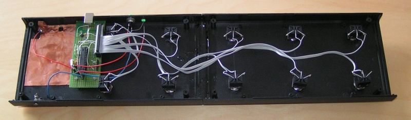
The pedal controller is built in the same way as in the first version.
As the footswitches I have used the
TL6520-112
switches, but it is possible to use e.g. PBS24-112 switch.
The electronic circuit is simple enough to fit into a simple standard prototype board.