
Do-It-Yourself V-USB MIDI Drum Trigger
Polska wersja tego dokumentu
In the Internet you can find a few descriptions how to build yourself a MIDI drum trigger.
For example you can visit the websites of the projects
Megadrum or
eDrum.
However I've decided to prepare yet another design, based on the following assumptions:
- It should be as simple as possible. The PCB should be single-sided and well suited
for thermotransfer technology. It should also be easy to mount even for the beginner,
therefore I've used integrated circuits in DIP enclosures.
- It should contain only easy to buy and cheap components - no exotic ICs are used.
- It should work with the USB interface - used both as a power supply and as
communication interface.
- It should be visible for a computer as an USB MIDI class device, to assure operation
with different aplications and different operating systems without any additional drivers.
- It should work with simple, easy to made percussion pads based on piezoelectric
transducers. It should also measure the hit velocity, and transmit it in the MIDI message.
Such controller may be easily used with applications like
Hydrogen, or lmms.
To ensure, that my controller is a USB MIDI class device, I have based my firmware on the
V-USB-MIDI project,
provided by Martin Homuth Roseman under the GPL license, which in turn
is based on the V-USB project
distributed under the GPL license by Objective Development Software GmbH.
Certainly my firmware is also available under the GPL license - you can
download the source, modify it and distribute
it under the same license.
The sources, with the history of last changes are also available
in the github repository.
To compile the source (with the AVR-GCC) just unpack
the sources, and run "make" in the "firmware" subdirectory. Command "make flash" allows you
to program the microcontroller (however you may need to adjust the makefile to your
programmer - now it is configured to use the original
usbasp programmer or
my modified version of usbasp)
The hardware part of my controller is prepared with the free and open source program
KiCad.
The complete KiCad project may be found here.
It is available as public domain.
Those, who don't want to install KiCad, may download the schematic diagram in the
PDF format.
The core of the controller is the ATmega88 chip. Because in the DIP enclosure it
offers only 6 analog inputs, I have added the 4051 analog mux/demux, which
increased the number of analog inputs up to 13.
Each input is connected to the input circuitry, matching the pulses generated by the piezo
transducers to the capabilities of the ADC converters.
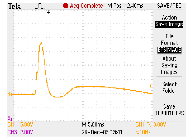
The piezo transducer, used by me generates after hit a positive pulse of length 1ms to 5ms,
and the smaller and longer negative pulse (sometimes more oscillations are visible).
 The ADC in ATmega88 may take c.a. 15000 samples per seconds. For 13 inputs we can measure
voltage on each input every c.a. 1 ms. To assure relaiable detection of the peak value,
and to provide correct operation even for inverse polarity of the transducer, a special
peak-to-peak detector is added on each input.
When building this circuit you may experiment with some values. E.g. the resistance
of potentiometers may be increased even up to 500kΩ.
Two diodes in series "on the right side" of the detector are used to increase the output voltage
and to improve the transfer function for weak hits.
To analyze how this circuit works, you can use the simulations
prepared for the free LTspice
program.
There are two simulations - each for different polarity of the transducer. The potentiometer
is simulated as two separate resistors - 20kΩ and 30kΩ.
The ADC in ATmega88 may take c.a. 15000 samples per seconds. For 13 inputs we can measure
voltage on each input every c.a. 1 ms. To assure relaiable detection of the peak value,
and to provide correct operation even for inverse polarity of the transducer, a special
peak-to-peak detector is added on each input.
When building this circuit you may experiment with some values. E.g. the resistance
of potentiometers may be increased even up to 500kΩ.
Two diodes in series "on the right side" of the detector are used to increase the output voltage
and to improve the transfer function for weak hits.
To analyze how this circuit works, you can use the simulations
prepared for the free LTspice
program.
There are two simulations - each for different polarity of the transducer. The potentiometer
is simulated as two separate resistors - 20kΩ and 30kΩ.
The printed board has been designed to fit the
KM48N enclosure.
If someone doesn't want to install KiCad, it is possible to
dowload the tracks and element layout in the PDF format.
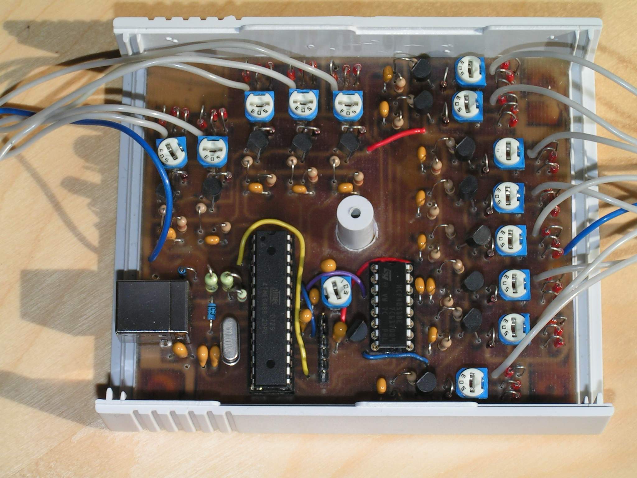
Please note, that this is really a single-side PCB. I have used the front layer only to show
connections which should be done with wires!
The assembled PCB, mounted in the enclosure is shown in the picture below:
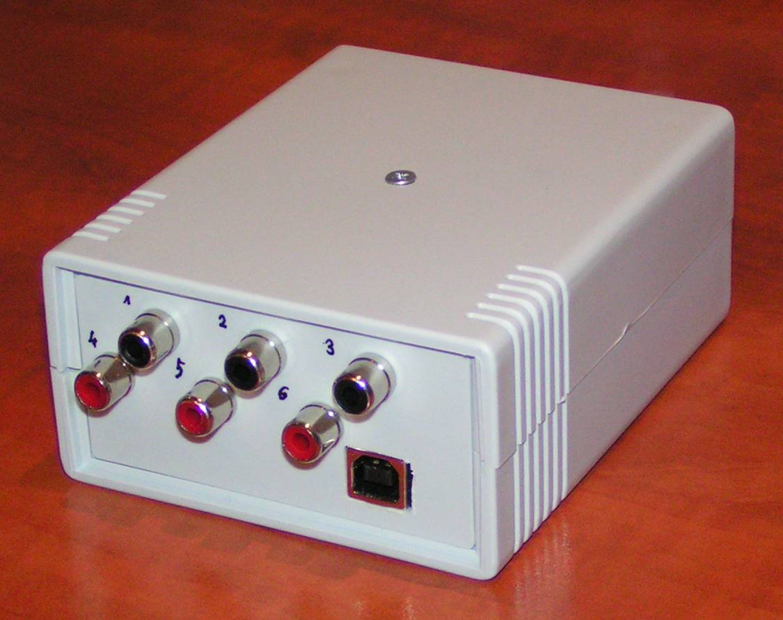
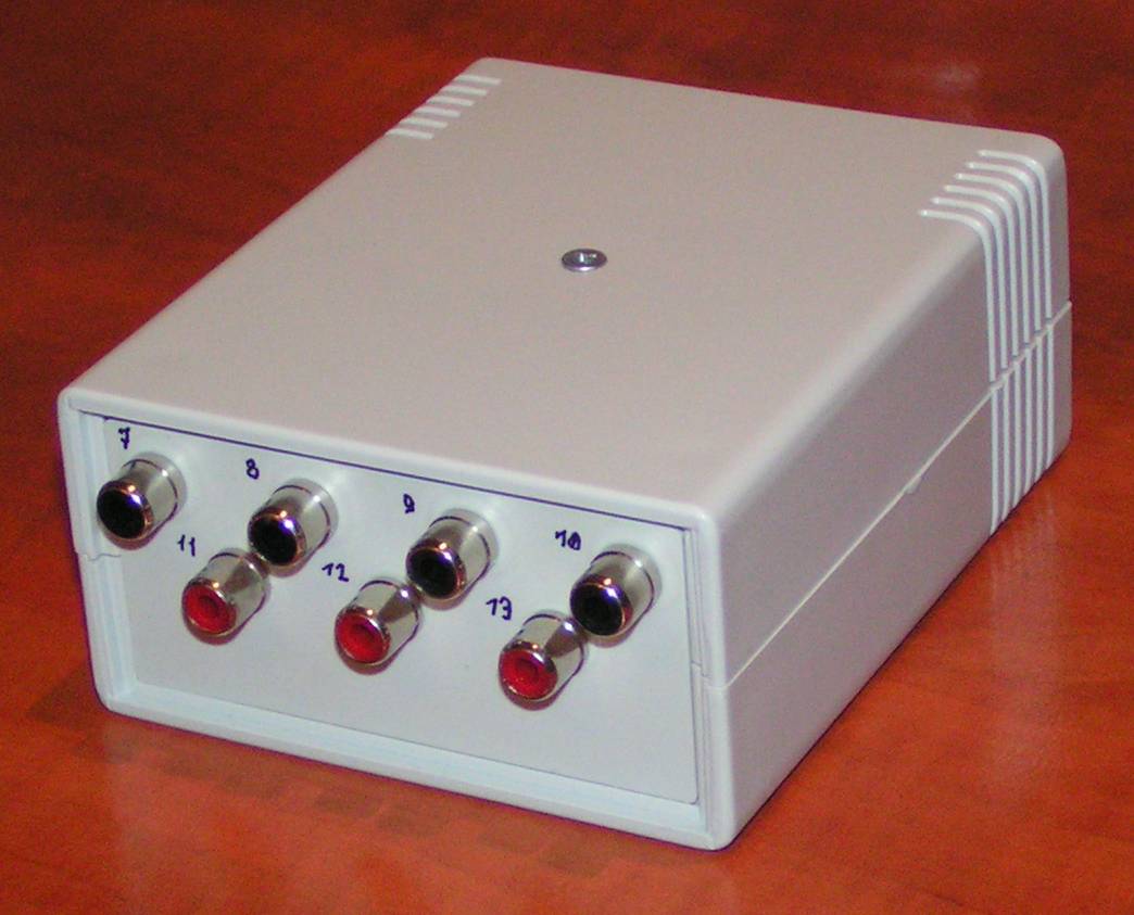
The complete controller is shown in the pictures below:
How to make simple percussion pads?
The best solution is to use professional pads, enhanced with the piezo transducers.
This method is described in different websites, e.g. in the following two:
The described controller works perfectly with such modified pads.
In my case however I coldn't use professional percusion stand and pads, both because of costs,
and because of space - the whole system should fit on the desk of my son ;-).
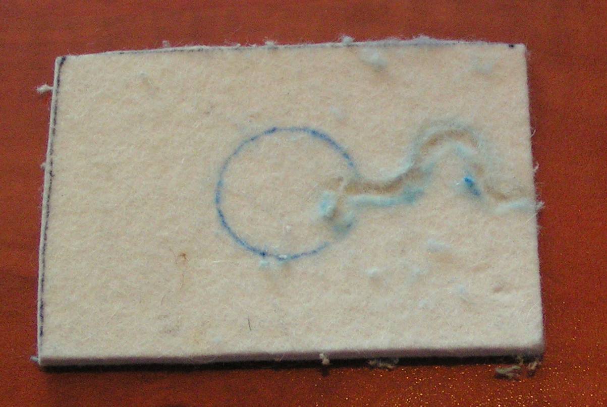
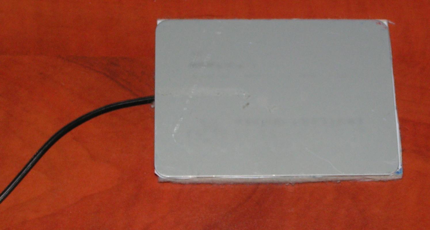
Therefore I have prepared very simple pads, using the metal plates, placed on the polish felt.
From the polish felt c.a. 5 mm thick, I have cut rectangles matching the shape of the metal plates
(65x95mm in my case). Then I have milled a channel for the shielded cabel. The channel
has a zig-zag shape to prevent tear-out of the cable.
The shielded cable is soldered to the piezo transducer - central wire to the "silver", central
part of the transducer (watch out not to overheat the silver electrode, as it may get damaged!),
the shield to the brass disc.
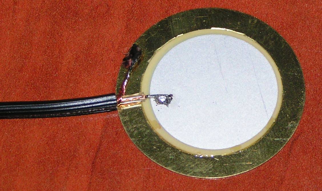
The second end of the cable is soldered to the Cinch plug. Part of the cable near to transducer
is fastened inside of the channel with stitches (watch out not to damage the cable when sewing!).
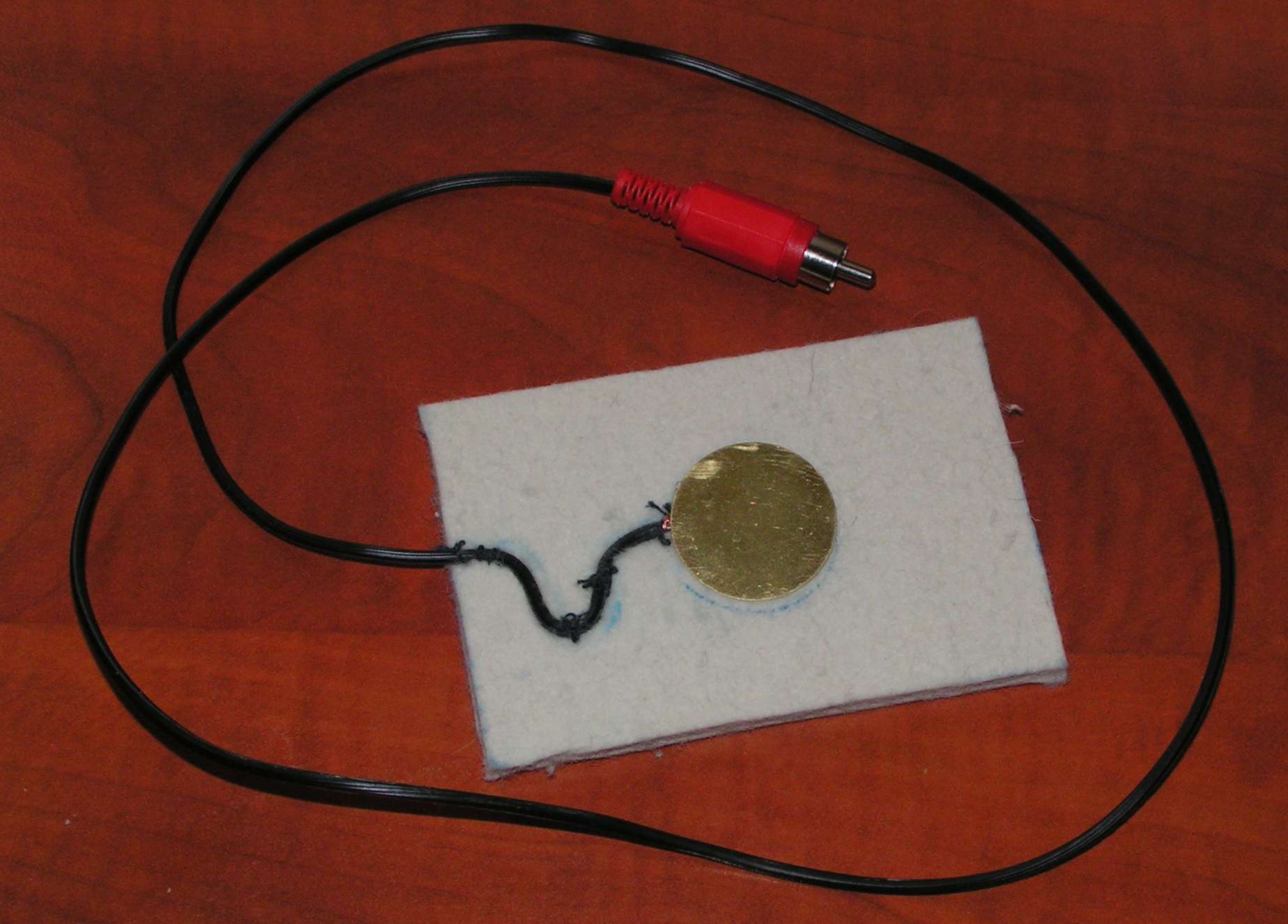
Finally the metal plate is covered with the two-side "strong" adhesive tape, and is placed
on the felt (so that the piezo converter is placed between the felt and the plate, with
brass disc sticked to the adhesive tape).
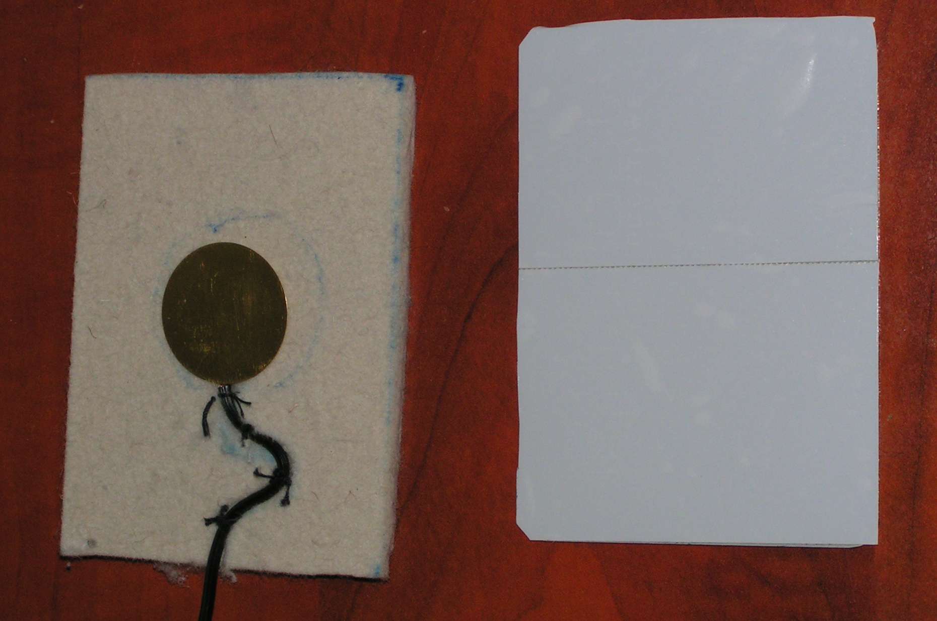
The ready to use pad is shown in the picture below.
You may cover the pad with the hard rubber or plastic to obtain more realistic touch.
My other MIDI related designs and programs
Wojciech Zabolotny