WZab's animated logo

USB interface for parallel port DSO-2100

This is the first, very rough version of the USB interface for my old, parallel port connected digital oscilloscope DSO 2100.

Disclaimer

The software described here is provided under the GPL license, without any warranty!
If you decide to use it, you are doing it on your own risk.
For example the DSO2100 uses the parallel port in the bidirectional mode, therefore the software bug, may cause both DSO and the PIC to drive the data lines simultaneously, which can lead to hardware damage.
The software has worked for me, but I can not warrant, that it will work on any system. It is also possible, that the files published on my site have got corrupted. So again: If you use it, you do it on your own risk!
The software is provided with all the sources, so I advise you to verify it, before the use.

USB ID Disclaimer

Because the USB<->DSO2100 interface is a free design, I was not able to obtain the legal vendor id and product id for it. Therefore it uses the bogus values: Vid=0xa5a5, Pid=0x0321. If you are going to distribute and/or sell any device based on it, you will probably need to obtain the legal Vid and Pid. Otherwise you will probably run into legal problems.

Software is provided mainly for Linux

Please note also, that the software is prepared mainly for Linux platform. Probably it may be used on other platforms (e.g. Windows) after some modifications, because the Python language is a multiplatform environment. However please don't ask me questions regarding the necessary modifications. I use Windows very rarely, and definitely I'm not an expert in it.

Hardware

Currently, as the hardware platform, I have used the didactical board developed for our students, based on the PIC18F4550 chip. The only addition required was a simple 25 PIN D-SUB F <-> IDC26 cable with the following connections:
LPT signalPIN in LPT conn.PIN in proto board connectorPIC signal
GND2425GND
D7922SPP7/RD7
D6821SPP6/RD6
D5720SPP5/RD5
D4619SPP4/RD4
D3518SPP3/RD3
D2417SPP2/RD2
D1316SPP1/RD1
D0215SPP0/RD0
STROBE114OESPP/RE2
AUTO1413CK2SPP/RE1
INIT1612CK1SPP/RE0
SELECT IN1711CSSPP/RB4
GND2010GND
The connections have been chosen so, that it is easy to solder the flat cable (folded between the wire soldered to pin 1 and the wire soldered to pin 14) to the pins of the 25 PIN D-SUB F connector.
Our didactical board requires the additional power supply, which in fact is not necessary, as the board in this application may be powered from the USB interface.
I'm going to design the dedicated simplified board for this interface, but it is not ready yet.
To get the interface working, you need two additional components:

The software is almost the same as in the version prepared for parallel port connection. In fact I'll try to combine both versions in a single package, which will on request load either the parallel port driver, or the USB driver.
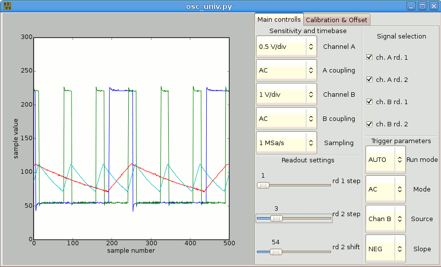
I have to apologize, but my GUI program is only a very simple "proof of the concept" software, oriented rather on the verification of the functions of the DSO2100, not on the building of the fully functional GUI.
Therefore the displayed values are expressed in the sample values and sample numbers, instead of volts and seconds or microseconds. The calibration settings dialog also uses the raw values (offset, v-offset, gain), instead of something more usefull. There is also no callibration routine (yet? hopefully...). However the GUI software is released under the GPL license, so you are free to modify it according to your needs.

Description of the USB firmware commands

DSO_GET_INFO (0x01)
Syntax: byte \x01
This command may be used to verify the version of the firmware. Should return "USB DSO-2100 GPL Interface 1.1" message
DSO_VERIFY_HW (0x02)
Syntax: byte \x02
This command checks, if the DSO 2100 is connected to the connector of the interface. Should return two character "\x55F" string (python syntax)
DSO_SEND_CMD (0x03)
Syntax: bytes \x03, cmd
This command sends the command to the DSO 2100. See the description, for the list of available commands
DSO_GET_STATUS (0x04)
Syntax: byte \x04
Gets the current status of the DSO 2100. Returns two character string. The first character is the status, the second one should be "b".
DSO_SEND_CMD_GET_STATUS (0x05)
Syntax: byte \x05, cmd
Not used, and not tested yet!
This command sends the command, and afterwards returns the current status.
DSO_SET_PARAMS (0x06)
Syntax: byte \x06, 15 bytes with the parameters' values
This command accepts the 15-byte long string with the values of consecutive parameters accepted by the DSO 2100. The order of the parameter is the following:
typedef struct {
uchar ack_chn; // offset 0
uchar smp_rate; // offset 1
uchar rd2_step; // offset 2
uchar rd1_step; // offset 3
uchar ch1_trig; // offset 4
uchar ch2_trig; // offset 5
uchar rd2_shift; // offset 6
uchar trig_slope; // offset 7
uchar ch1_v_offset; // offset 8
uchar ch2_v_offset; // offset 9
uchar trig_level; // offset 10
uchar ch1_offset; // offset 11
uchar ch1_gain; // offset 12
uchar ch2_offset; // offset 13
uchar ch2_gain; // offset 14
} dso_params;
DSO_SET_PARAM (0x07)
Syntax: byte \x07, offset, value
Not used, and not tested yet!
This commands sets the aparameter at the particular offset
DSO_START_ACQ (0x08)
Syntax: byte \x08, channel, LSbyte_of_timeout, MSbyte_of_timeout
This command starts the acquisition in the given channel (1 or 2). The current implementation is rather messy, as this command was supposed to be used both for starting the acquisition, and for restarting it when trigger is rare, or when auto trigger is provided. I hope to clean it up in the next version.
DSO_GET_DATA (0x09)
Syntax: byte \x09, num_of_samples,channel
This command requests the given (up to 250 samples) amount of data from the selected channel (1 or 2).

Wojciech M. Zabolotny
Last modified: Sun Dec 23 20:13:32 CET 2007