
Open PIC Lab
This site presents a simple didactical microcontroller modules designed for teaching of
microcontroller systems, digital signal processing, and system programming.
Full documentation (schematic diagram and pcb design) is provided, and you
are free to duplicate the modules. However, if you are going to
use THESE schematic or PCB files to build and distribute the modules,
than you should include the information about the original source and
about the availability of the documentation.
Currently two modules are available:
PIC18F4550 module
Parameters:
- Clock frequency up to 48MHz (12 MIPS) with oscilator working at 8 MHz
- Memory: 2KB RAM, 256 B EEPROM, 32KB code (FLASH)
- USB 2.0 Interface - Low Speed & Full Speed
- 10-bit ADC (7 channels available for user)
- 2 analogue comparators
- 4 timers and 2 PWM/CCP modules (one extended)
- Synchronous/asynchronous serial interface (EUSART)
- Synchronous serial interface: SPI/I2C
- Parallel SPP port - for direct transfer of data over USB
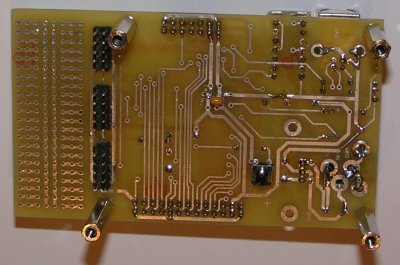
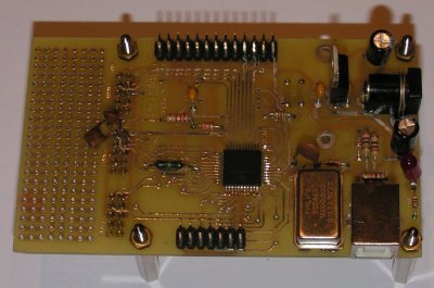
 This module is based on the PIC18F4550 microcontroller.
It offers the direct USB connectivity.
Available documentation includes the schematic diagram as PDF,
sources of the schematic diagram in the
gschem format,
and the PCB layout in the
free PCB program format.
This module is based on the PIC18F4550 microcontroller.
It offers the direct USB connectivity.
Available documentation includes the schematic diagram as PDF,
sources of the schematic diagram in the
gschem format,
and the PCB layout in the
free PCB program format.
dsPIC30F6014 module
Parameters:
- Clock frequency up to 120MHz (30 MIPS) with oscilator working at 8 MHz
- Memory: 8KB RAM, 4 KB EEPROM, 144KB code (FLASH)
- 16-bit DSP core, with mostly one-cycle instructions
- 12-bit ADC (up to 100Ksps),14 channels available for the user
- Flexible interrupt system with 8 priority levels
- USB connectivity (using the dsPIC UART and FT232BM UART to USB converter)
- The second UART available for the user
- 2 analogue comparators
- 5 16-bit timers (may be joined into 32-bit timers)
- DCI Interface
- 2 SPI Interfaces & 2 CAN interfaces
- Input Capture Module (6 inputs available for the user, other shared with other interfaces)
- Output Compare Module (8 outputs available for the users, other shared with other interfaces)
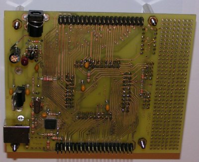
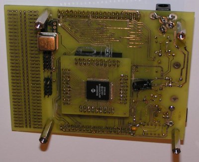
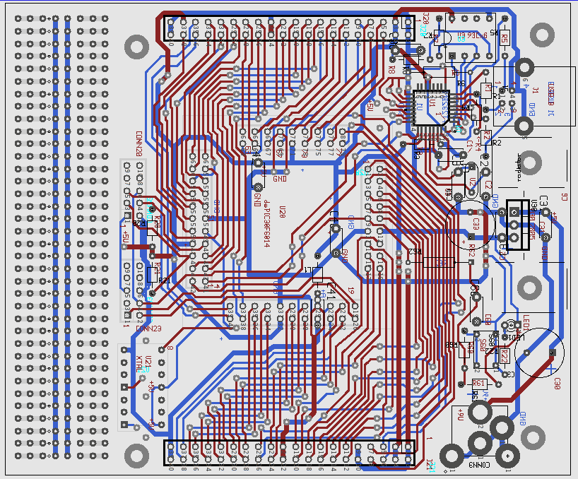 This module is based on the dsPIC30F6014 microcontroller/digital signal processor.
The processor is placed on the daughterboard to allow easy replacement.
The USB connectivity is assured by the additional FTDI FT232BM chip.
Available documentation includes the schematic diagram
as PDF,
sources of the schematic diagram in the
gschem format,
and the PCB layout in the
free PCB program format.
This module is based on the dsPIC30F6014 microcontroller/digital signal processor.
The processor is placed on the daughterboard to allow easy replacement.
The USB connectivity is assured by the additional FTDI FT232BM chip.
Available documentation includes the schematic diagram
as PDF,
sources of the schematic diagram in the
gschem format,
and the PCB layout in the
free PCB program format.
The daughterboard PCB layout is also available.
PIC programmer for LPT port
To enable programming of the above boards a simple programmer has been
developed.
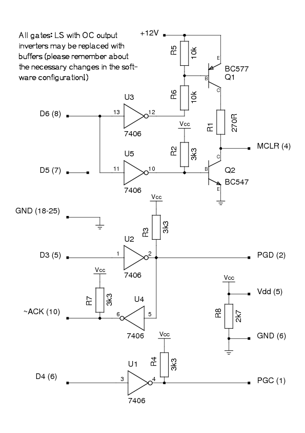 The programmer has been mounted on a prototyping board. Therefore no PCB
layout is available. However you can download the schematic diagram
in the PDF format or the sources
in the gschem format.
The programmer has been mounted on a prototyping board. Therefore no PCB
layout is available. However you can download the schematic diagram
in the PDF format or the sources
in the gschem format.
The programmer may be used with the
WinPic
program under Windows, using the
following configuration file (please note,
that this file is valid for 74LS07 in the programmer, for 74LS06 you need
to invert signals). However when using it
under Windows XP we've experienced frequent problems caused by
collisions between the WinPic and
the printing subsystem of Windows
(announced as "WARNING: Windows fooled around with the LPT port bits").
The preferred solution is to use the
newest version of the Odyssey program (improved by
Pierre Gaufillet) under Linux which is able to
program the PIC18F4550 chips, when using this config
file (should be placed as ~/.odyssey/config on the user's machine).
Unfortunately no Linux based solution for dsPIC is ready yet.
Some work on adaptation of
dspicprg for our
programmer is on the way, but it has not been completed yet.
keyboard-display module
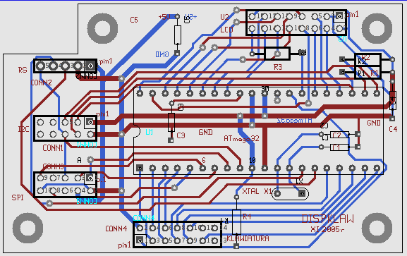 This auxiliary module allows to connect an additional keyboard and LCD display
to any of the above modules. The communication between the microcontroller module
and the keyboard/display module is possible either via asynchronous interface or via
the I2C (TWI) interface.
Available documentation includes the schematic diagram
as PDF,
sources of the schematic diagram in the
gschem format,
and the PCB layout in the
free PCB program format.
This auxiliary module allows to connect an additional keyboard and LCD display
to any of the above modules. The communication between the microcontroller module
and the keyboard/display module is possible either via asynchronous interface or via
the I2C (TWI) interface.
Available documentation includes the schematic diagram
as PDF,
sources of the schematic diagram in the
gschem format,
and the PCB layout in the
free PCB program format.
Designs based on our OPICLAB boards
- based on PIC18F4550
- based on dsPIC30F6014
wzab
Last modified: Tue Nov 6 22:34:08 CET 2007