
PICADC - a free, PIC based "intelligent" A/D converter
This is an old design. Some of the components may be difficult to buy.
If you would like to build an even better and cheaper A/D converter, take
a look at the new PICADC3 design.
The PICADC is a simple 12-bit, 8-channel analog to digital converter
(with 4 additional digital inputs), which may be
connected to the PC through the serial interface (RS232).
The sequence of sampled channels, and sampling frequence are programmed by the PC.
The maximal sampling frequency is limited by the data transmission rate,
and at 115200 baud is equal to ca. 3kHz for 1 channel without digital inputs, and to
ca. 500 Hz for 8 channel with digital inputs.
The analog input voltage range is -2.5V to 2.5V.
The digital inputs may be used for recording additional digital signals, eg.
the time code used to synchronize the recorded data with other events.
The PICADC is based on PIC16F84 (or 166C84) microcontroller, and MAX190
(or MAX191) ADC.
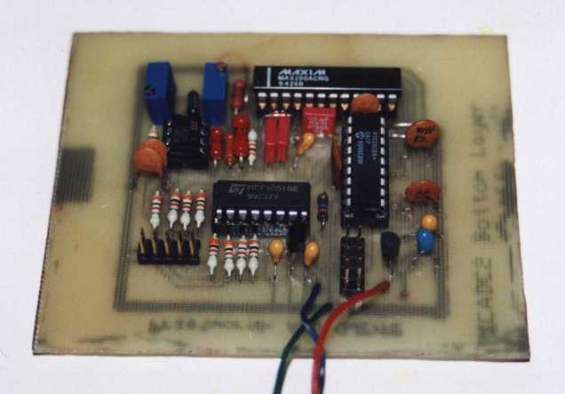
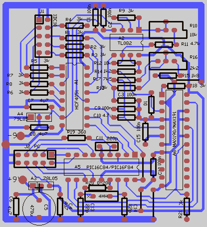
The device is mounted on a small single-sided printed board, easy to prepare
even at home, shown in the figure
below (and available
in the
Easytrax for DOS
format).
There also printouts of the bottom layer,
and top overlay available in the PDF format
The schematic diagram of PICADC is shown in the picture below, and
is also available in the PDF format.
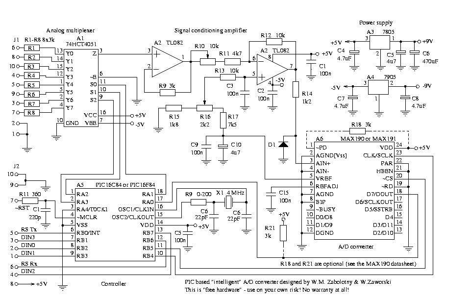
The R18 and R21 resistors are not mounted on my board. The R18 may be used to
change the compensation mode of internal voltage reference in MAX190/191
(see the MAX190/191 data sheet), and R21 may be used to pull up the data line,
when MAX190's DOUT is in high impedance state.
The 4u7 capacitors (C4, C5, C7, C8, C10) should be tantalium capacitors
(watch the polarity, when mounting them!).
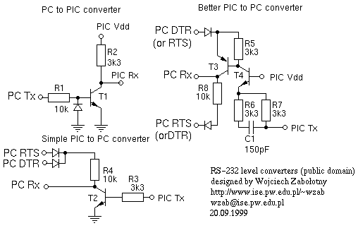
The PICADC was intended to be a part of an optoisolated data acquisition system.
Therefore its PCB does not contain the RESET circuitry and RS level converters,
which should be connected through the transoptors. However usually the RESET switch
is not needed and you can connect the ~RST pin (7) in the J2 connector to the +5V
(J2 pin 8). If the optoisolation is not needed, you can use the MAX232 as the level
converter, or simple circuits shown in the figure below:
The PIC software is available in the source form,
and as precompiled HEX files for
PIC16C84
and for PIC16F84.
The communication protocol
The PICADC is connected to the serial port of the PC computer.
In the first step, the PC sends the BREAK signal (ca. 0.5 sec long) to reset the
PICADC. Then PICADC sends the identification string, using the 19200 baud, 8 bit,
no parity mode. In the current version, the identification string is
WZPICADC100003. After receiving the valid identification string, PC
should send the 14 configuration bytes (using the above mode). Meaning of the
configuration bytes is summarized in the table below:
| Byte no |
Meaning |
| 1 |
Number of channels |
| 2 |
Channels table
Each entry is equal to channel number (0..7) times two |
| 3 |
|
| 4 |
|
| 5 |
|
| 6 |
|
| 7 |
|
| 8 |
|
| 9 |
|
| 10 |
fdel - fine delay (0 to 0x80) |
| 11 |
del0 - rough delay, byte 0 (0 to 0xff) |
| 12 |
del1 - rough delay, byte 1 (0 to 0xff) |
| 13 |
del2 - rough delay, byte 2 (0 to 0xff) |
| 14 |
cflags - configuration flags
- bit 7 - if set, data are transmitted at 115200 baud
- bit 6 - if set (and bit 7 is 0), data are transmitted at 57600 baud.
If both bits 6 and 7 are 0's, data are transmitted at 38400 baud
- bits 1 to 5 - unused
- bit 0 - If set, digital inputs are not used
|
After reception of the configuration bytes, the PICADC calculates the 8-bit
checksum of the received data (see the sources for details of the algorithm),
and sends it back to the PC, which compares it to the
checksum calculated from the original data. If the checksums match, PC assumes that
the configuration bytes have been received correctly, and the PICADC is ready.
PC changes the serial port's mode to the 115200, 57600 or 38400 baud (according to
the cflags), 8 bit, even parity, and sends the "0" byte, to start the data
acquisition.
The PICADC starts to sample the input signals and send the data to the PC.
The data consist of records with 12-bit words packed by two in three bytes
words as follows:
| byte 0 |
byte 1 |
byte 2 |
| A11 |
A10 |
A9 |
A8 |
A7 |
A6 |
A5 |
A4 |
A3 |
A2 |
A1 |
A0 |
B3 |
B2 |
B1 |
B0 |
B11 |
B10 |
B9 |
B8 |
B7 |
B6 |
B5 |
B4 |
If the number of channels is odd, last channel uses two bytes.
If the digital inputs are used, an additional byte is added, containing the
digital signals values:
| b7 |
b6 |
b5 |
b4 |
b3 |
b2 |
b1 |
b0 |
| DIN3 |
DIN2 |
DIN1 |
DIN0 |
Record number |
The 4-bit record number increases by 1 (modulo 16) after each record.
Checking of this
value is very usefull for detection of data loss due to the serial data overrun
or hardware faults. Therefore it is recommended to use digital inputs, always
when the required sampling rate is low enough.
Sampling period definition
The sampling timing is synthesized fully by the software. No interrupts are used,
so the sampling timing is jitter free. However such method complicates the
calculation of sampling period.
Additionally most modifications of PIC's code require to modify at least the values
used for calculation of sampling period (see the tables below) and sometimes even
the formulas.
For the original version of PIC's code and for 4 MHz oscillator
the sampling period Tsmp is defined
by the formula:
Tsmp = tanlg + tdig + tdel
The tdig is the time used for sampling and transmission of digital inputs.
It depends only on transmission baudrate, according to the table below.
The tanlg is the time used for sampling of analog channels, and depends
on number of sampled channels (nch) and transmission baudrate,
according to the formulas below:
For odd nch: |
tanlg = todd+(nch - 1) * tstep / 2 |
For even nch: |
tanlg = tev+(nch - 2) * tstep / 2 |
Where tstep, todd and tev depend on the transmission
baudrate according to the table below.
| Baud rate [baud] |
tdig [usec] |
tstep [usec] |
todd [usec] |
tev [usec] |
| 115200 |
111 |
453 |
311 |
488 |
| 57600 |
208 |
744 |
505 |
779 |
| 38400 |
302 |
1026 |
693 |
1061 |
The tdel is the time of execution of an additional delay loop, used
to achieve the required sampling period. It is defined by the formula:
tdel = (128 - fdel) +
10 * (255 - del0) +
2560 * (255 - del1) +
655360 * (255 - del2) [usec]
The sample program
To help understand PICADC, I've prepared a
sample data recording programm
for Linux operating system.
It is very simple application, and the only thing it can do is to
sample analog and digital inputs at the specified frequency and to write
the acquired data in the ASCII comma delimited format to the file or
to the screen.
Command line parameters
The proper command line to call the sample program is:
picadc [options]
To quit the program, you should press the CTRL+C key
The options are as follows:
- -o
- This option specifies the output file, where the recorded
data are stored. If the "-o" option is not used, then tha recorded
data are written to the stdout.
eg. -o output_file.txt
- -1
- This option sets the data transmission baud rate to 115200 baud.
Remember, that the configuration of PICADC is performed always
on 19200 baud. This option, and "-3", "-5" options affect only
the transmission of acquired data.
- -5
- This option sets the data transmission baud rate to 57600 baud.
- -3
- This option sets the data transmission baud rate to 38400 baud.
Warning! Remember that in Linux the 38400 is used for very
strange things. Eg. to allow older applications to use higher, or
nonstandard baud rates, it is possible to use the
setserial utility to "redefine" the 38400 baudrate.
See the documentation of setserial utility, the
spd_hi, spd_vhi, spd_cust and spd_normal options.
- -t
-
This option sets the TTY device, the PICADC is connected to.
eg. -t /dev/ttyS1
- -c
-
This option specifies the list of analog channels. It should be
followed by the comma separated list of channels' numbers (up to 8,
channels are numbered from 0 to 7) in sampling order.
eg. -c 4,2,5
- -d
-
This option tells the PICADC to skip digital inputs sampling. Use this
option only when it is absolutely necessary to achieve the required
sampling rate, because the record count, transmitted together with
the digital inputs data is very usefull to verify the correctness
of data transmission.
- -s
-
This option specifies the sampling period in microseconds.
Remember, that this is the sampling period of the whole channels set
(not the amount of time between sampling of consecutive channels
in the set). The channels are not sampled simultaneously, however,
because use of S/H buffer in each channel would be too expensive.
Such solution introduces a phase shift between the channels, and if
it is important for you, you should consider the time delays between
the sampling of particular channels. You can find this delays by
simulating the PICADC's software in MPLAB.
eg. -s 10000 results in sampling frequency equal to 100 Hz for
each channel.
Possible improvements
It is possible to eliminate the external ADC and multiplexer, if PIC
with integrated 12-bit ADC (eg. 16C774) is used. However in this case
you should provide separate signal conditioning amplifiers for each
channel (but in this case you may obtain the input voltage range
difficult to realize with standard analog multiplexers - eg. ± 10V).
It is possible to use one only signal conditioning amplifier (and
elimination of external ADC) if external multiplexer is still used
(in this case only one channel of internal
ADC is used). Unfortunately I was unable to test the above solutions,
because of unavailability of windowed 16C774.
It is possible to increase the amount of analog channels to 16 by using of HEF4067
or two 4051's with an additional inverter. In this case the RA4 pin
(pulled up with 3k resistor) should be used to drive the fourth address line.
RSCALC utility
When writing the RS232 transmission routines for different baud rates, I prepared
a small utilities for displaying of asynchronous transmission timings for different
speeds. It is really very simple, but maybe you'll find it usefull.
Here is the source.
License and warranty disclaimer
PICADC is a free hardware. You can copy it, modify and use for any
(even commercial) purposes without paying any fee.
The only requirement is that if you prepare a derived work based on PICADC
(or just modified version), or if you distibute it,
you should provide the information about the authors of original version
(Wojciech Zabolotny [wzab@ise.pw.edu.pl] and
Wojciech Zaworski [zawor@ise.pw.edu.pl]).
The accompanying software is available under the
"Artistic License".
Because PICADC is free, we do not give you any warranty!
We don't know if using of PICADC for any particular purpose may infringe someone's
patent. We don't know if in some porticular conditions it can destroy your
computer or connected hardware.
You use it on your own risk!
Please send any comments, improvements or suggestions to:
Wojciech Zabolotny
Last modified: Fri Oct 8 15:12:04 CEST 1999