
Free PIC 16x84 programmer with margining support
 Although there are many free programmers for
PIC16x84 microcontrollers,
most of them (see the exception list)
do not support so called "margining" - verifying of programmed
contents at different power supply voltages.
Therefore I've decided to propose a very simple programmer, able to
programm and verify the PIC's memory at programmed VDD.
The programmer is provided as "free hardware". You can reproduce it
and use for any
purpose, (even commercial) without paying any fee, but please provide
the information about the authors.
Although there are many free programmers for
PIC16x84 microcontrollers,
most of them (see the exception list)
do not support so called "margining" - verifying of programmed
contents at different power supply voltages.
Therefore I've decided to propose a very simple programmer, able to
programm and verify the PIC's memory at programmed VDD.
The programmer is provided as "free hardware". You can reproduce it
and use for any
purpose, (even commercial) without paying any fee, but please provide
the information about the authors.
This is "free hardware". We do not give you any warranty.
You connect this device to your computer and your PIC controller at your
only risk. We may not assure you, that it will not blow your PC
up :-).
Description
The schematic diagram is available as a
gzipped EPS file and as a
PDF file.
The PIC's power suply voltage is set by three lowest bits of printer data,
as described in the table below:
| D0 | D1 | D2 | VDD
|
| 1 | x | x | 0 V |
| 0 | 0 | 0 | 6 V (VDD max) |
| 0 | 1 | 0 | 5 V (VDD progr) |
| 0 | 0 | 1 | 4 V (VDD min) |
With other resistors values, the programmer may be used for "extended
voltage range" series of PIC controllers.
Adjustment procedure
Set all data bits in the printer port to "0", and adjusting
the RV1, set PIC VDD to VDD max.
Then set D0=0, D1=1, D2=0 and adjust the RV3, to get the nominal VDD on
PIC VDD output.
Finally set D0=0, D1=0, D2=1 and adjust the RV2, to obtain the VDD min
on the PIC VDD output
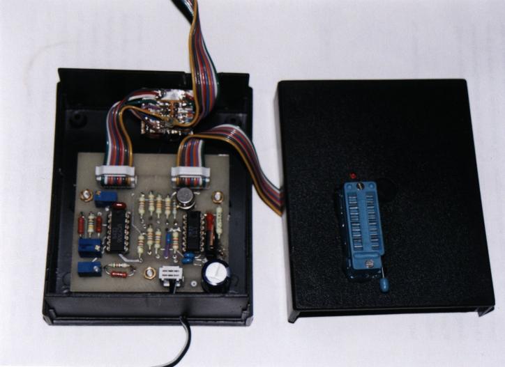
The printed board
The printed board in gzipped
Easytrax
format was prepared by
Wojciech Zaworski
.
The gzipped PostScript printouts of
bottom layer,
top layer and
top overlay are available.
I will be gratefull if someone prepares the printed board in the
GPL PCB format.
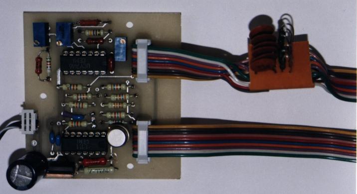
If you are going to connect the programmer to the PC with a long flat
ribbon cable, you should consider using the additional RC-filters (they
are not implemented on the PCB). See the schematic diagram.
In the picture below you can see the main PCB with the RC-filters mounted
on a small additional PCB.
The software
There are two programms available for our programmer.
Both of them work in Linux OS.
The first program "mp84" is written by
Michal Pleban, and is available under
the GPL license. You can download:
- Sources in tgz format
- Sources in SRPM format
- Binaries in RPM format
The second way to use this programmer is
a "quick and dirty"
patch for the
Brian C. Lane's programming software.
To get the software working with our programmer you should:
- Download the
original picprg sources
- Uncompress them with "tar -xzf picprg.2.2.tar.gz"
- Download the patch
- Apply the patch with "gzip -dc picprg.2.2.wz.diff.gz | patch -p0"
If the patch gets uncompressed during the dwonloading
(Netscape does this), you should apply the patch with
"patch -p0 < picprg.2.2.wz.diff"
- Compile the software "cd picprg.2.2; make"
- As root make "chown root picprg; chmod u+s picprg"
The Vdd level controlling pins (3 [D1] and 4 [D2]) are hardcoded into the
software (I didn't decide to modify the GUI so seriously).
In the configuration menu you may switch the Vdd level
with "<" (Vdd min) "=" (Vdd norm) and ">" (Vdd max) keys.
The rest of pins are configured by the GUI, and should be set as follows:
- Vpp control pin #: -[07]
- Vdd control pin #: -[02]
- Clock pin #: -[05]
- Data to PIC pin #: -[06]
- Data from PIC pin #: +[11]
In the main menu of the modified PICPRG there are two verification options:
- [V] Verify PIC with RAM at Vdd max
- [B] Verify PIC with RAM at Vdd min
Warning
On my Linux box it happens sometimes, that when I run the picprg,
the PIC's Vdd gets
on (up to this time I have not found the reason).
Inserting of PIC in the socket in this condition may be dangerous.
Therefore I recommend adding LED (with a 3k resistor) connected between
the GND and Vdd pins, to be warned about such a situation.
Chosing the [C] option, and exiting the configuration menu switches the Vdd
off, and then it is safe to insert the PIC.
What should be done in the future
We are planing a few improvements in the near future:
- Add support for four Vdd voltage levels (6V, 5V, 4V and 2V) to allow
full verification of low power PIC's.
Because the 16F87X family requires additionally the 5.5V voltage,
amount of individually adjusted voltage levels becomes unacceptable -
I consider designing a new version of programmer with DAC-regulated
power supply voltage. Any suggestions are appreciated.
- Redesign the PCB to add the function mentioned above, to include
the filters on the main PCB, and to change the PCB format from
Easytrax
to the GPL PCB.
- Improve the software (add the full support to the PICPRG2.2, or write
a new software from the scratch).
- WISP
(designed by Wouter van Ooijen)
If you know about other such designs, please
let me know...
Please send any suggestions or comments to me.
Wojciech Zabolotny

[Skip Prev]
[Prev]
[Next]
[Skip Next]
[Random]
[Next 5]
[List Sites]
[Join Ring]
Last modified: Tue Mar 7 15:33:18 CET 2000